Analogue multimeters


Analogue meters take a little power from the circuit under test to operate their pointer. They must have a high sensitivity of at least 20k ohm /V or they may upset the circuit under test and give an incorrect reading. See the section below on sensitivity for more details
Batteries inside the meter provide power for the resistance ranges, they will last several years but you should avoid leaving the meter set to a resistance range in case the leads touch accidentally and run the battery flat
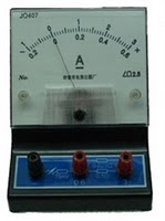
Typical ranges for analogue multimeters like the one illustrated:
(the voltage and current values given are the maximum reading on each range)
DC Voltage: 0.5V, 2.5V, 10V, 50V, 250V, 1000V.
AC Voltage: 10V, 50V, 250V, 1000V.
DC Current: 50µA, 2.5mA, 25mA, 250mA.
A high current range is often missing from this type of meter.
AC Current: None. (You are unlikely to need to measure this).
 Resistance: 20 ohm , 200 ohm , 2k ohm , 20k ohm , 200kohm
 
These resistance values are in the middle of the scale for each range
 
It is a good idea to leave an analogue multimeter set to a DC voltage range such as 10V when not in use. It is less likely to be damaged by careless use on this range, and there is a good chance that it will be the range you need to use next anyway

Digital multimeters


All digital meters contain a battery to power the display so they use virtually no power from the circuit under test. This means that on their DC voltage ranges they have a very high resistance (usually called input impedance) of 1M ohm or more, usually 10M ohm , and they are very unlikely to affect the circuit under test.
Typical ranges for digital multimeters like the one illustrated:
(the values given are the maximum reading on each range)


DC Voltage: 200mV, 2000mV, 20V, 200V, 600V.
AC Voltage: 200V, 600V.
DC Current: 200µA, 2000µA, 20mA, 200mA, 10A*.
*The 10A range is usually unfused and connected via a special socket.

AC Current: None. (You are unlikely to need to measure this).

Resistance: 200ohm, 2000ohm, 20kohm, 200kohm, 2000kohm, Diode Test
 

Digital meters have a special diode test setting because their resistance ranges cannot be used to test diodes and other semiconductors

Ammeters and Voltmeters


The Ammeter


The ammeter is an instrument used to measure electrical current. To measure the current flowing through some point of a circuit, the circuit must be broken open at that point and the ammeter inserted so that the current to be measured actually flows through the meter too. (Note: Turn off the power before inserting the ammeter, then restore the power to make the current reading.) To reiterate: to measure the current flowing through a circuit element, the circuit must be opened and the ammeter put in series with it. See the top two circuits of Fig. 4 for examples of correct ammeter placement


Most meters have a number of possible settings for the maximum possible current that can be measured; for example: 2 A, 200 mA, 20 mA, 2 mA. You should always start by turning the setting to the highest possible rating (for example, 2 A). When the meter is finally situated in the circuit to take the reading, and the power is turned on to the circuit, the sensitivity of the ammeter may be increased by changing to progressively lower ranges. It is important not to overshoot the maximum value that can be read. For example, if the current is about 75 mA, then the ammeter would be set to the 200 mA scale for the most accurate reading; setting to the 20 mA scale would overload the ammeter and most likely open its internal fuse. Golden rule of multimeters: Return to voltmeter mode immediately after use as an ammeter is completed

The Voltmeter


The potential difference, or change in electric potential, between two points is measured with a voltmeter. Current flows through a resistor because of a potential difference applied by a battery or power supply. Potential difference is commonly measured in units of volts (V) or millivolts (mV = 10-3 V). Common usage refers to a potential difference relative to ground (0.0 V) as simply the voltage, though it is prudent to call it by its correct name to emphasize the way it is measured. The potential difference across a circuit element is measured by placing the two leads of a voltmeter on the two sides of the element. Look again at the lower two diagrams in Fig. 4. The voltmeter remains "to the side"; its removal will not change the circuit. Notice the difference in ammeter use where the meter becomes an integral part of the circuit being measuring. The removal of a correctly used ammeter would stop current flow in at least part of the circuit by creating an open condition

How does an oscilloscope work?


An outline explanation of how an oscilloscope works can be given using the block diagram shown below
   
Like a televison screen, the screen of an oscilloscope consists of a cathode ray tube. Although the size and shape are different, the operating principle is the same. Inside the tube is a vacuum. The electron beam emitted by the heated cathode at the rear end of the tube is accelerated and focused by one or more anodes, and strikes the front of the tube, producing a bright spot on the phosphorescent screen
The electron beam is bent, or deflected, by voltages applied to two sets of plates fixed in the tube. The horizontal deflection plates, or X-plates produce side to side movement. As you can see, they are linked to a system block called the time base. This produces a sawtooth waveform. During the rising phase of the sawtooth, the spot is driven at a uniform rate from left to right across the front of the screen. During the falling phase, the electron beam returns rapidly from right ot left, but the spot is 'blanked out' so that nothing appears on the screen
In this way, the time base generates the X-axis of the V/t graph
The slope of the rising phase varies with the frequency of the sawtooth and can be adjusted, using the TIME/DIV control, to change the scale of the X-axis. Dividing the oscilloscope screen into squares allows the horizontal scale to be expressed in seconds, milliseconds or microseconds per division (s/DIV, ms/DIV, µs/DIV). Alternatively, if the squares are 1 cm apart, the scale may be given as s/cm, ms/cm or µs/cm
The signal to be displayed is connected to the input. The AC/DC switch is usually kept in the DC position (switch closed) so that there is a direct connection to the Y-amplifier. In the AC position (switch open) a capacitor is placed in the signal path. As will be explained in Chapter 5, the capacitor blocks DC signals but allows AC signals to pass
The Y-amplifier is linked in turn to a pair of Y-plates so that it provides the Y-axis of the the V/t graph. The overall gain of the Y-amplifier can be adjusted, using the VOLTS/DIV control, so that the resulting display is neither too small or too large, but fits the screen and can be seen clearly. The vertical scale is usually given in V/DIV or mV/DIV
The trigger circuit is used to delay the time base waveform so that the same section of the input signal is displayed on the screen each time the spot moves across. The effect of this is to give a stable picture on the oscilloscope screen, making it easier to measure and interpret the signal
Changing the scales of the X-axis and Y-axis allows many different signals to be displayed. Sometimes, it is also useful to be able to change the positions of the axes. This is possible using the X-POS and Y-POS controls. For example, with no signal applied, the normal trace is a straight line across the centre of the screen. Adjusting Y-POS allows the zero level on the Y-axis to be changed, moving the whole trace up or down on the screen to give an effective display of signals like pulse waveforms which do not alternate between positive and negative values